Regarding pin assignment of m-pod

Hello.

I am using StimTracker Quad with m-pod for parallel port to send stimulus triggers to an MEG device.
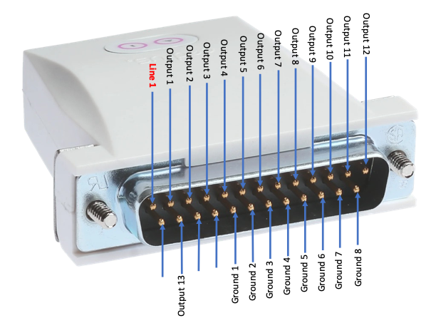
With StimTracker 1G the pin assignments are explicitly described (StimTracker Output Pin Assignments) and I was wondering if there is a similar description for the device I am using.
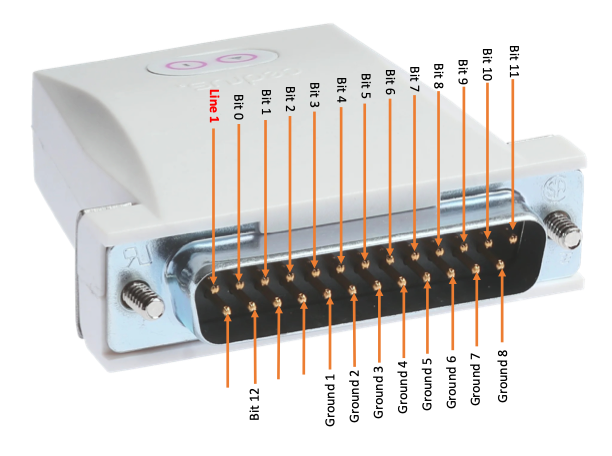
Pin assignments for m-pod can be configured using Xidon software but I am having difficulty with corresponding the Xidon software and m-pod’s 25 pins. Furthermore, are/is certain pin(s) dedicated for grounding like in StimTracker 1G?(if so, which pins are assigned for grounding?)

I am new to using the product so I am sorry if answers to my question is already documented or answered in this forum.

Thank you in advance.

We have recently realized that we are missing a description of the output pins for “m-pod for Parallel Port”. I apologize for this omission.

m-pod for Parallel Port produces thirteen bits of output on lines 2 to 13 and line 15. Pins 18 to 25 are all connected to ground.

Thank you so much for your reply.

Just for confirmation of my understanding, are pins assigned as shown in the attached image? Additionally, is line 1 assigned to anything?
m-pod pin assignment

Thank you in advance.

My apologies for the consecutive message.
I would like to make sure about the bit assignment. Are bits assigned correctly in the following schematics?
m-pod pin assignment

Again, thank you for your time.

Your diagram is correct. Line 1 is not connected to anything.

1 Like